Showing posts with label tester. Show all posts
Showing posts with label tester. Show all posts
Tuesday, April 9, 2013
Voltage Tester for Model Batteries
With a suitable load, the terminal voltage of a NiCd or lithium-ion battery is proportional to the amount of stored energy. This relationship, which is linear over a wide range, can be used to build a simple battery capacity meter.
Circuit Image :

Voltage Tester for Model Batteries Circuit Image
This model battery tester has two functions: it provides a load for the battery, and at the same time it measures the terminal voltage. In addition, both functions can be switched on or off via a model remote-control receiver, to avoid draining the battery when it is not necessary to make a measurement. The load network, which consists of a BC517 Darlington transistor (T2) and load resistor R11 (15 Ω /5 W), is readily evident. When the load is active, the base of T1 lies practically at ground level. Consequently, T1 conducts and allows one of the LEDs to be illuminated.
Circuit Diagram :
Voltage Tester for Model Batteries Circuit Diagram
The thoroughly familiar voltmeter circuit, which is based on the LM3914 LED driver, determines which LED is lit. The values of R6 and R7 depend on the type and number of cells in the battery. The objective here is not to measure the entire voltage range from 0 V, but rather to display the portion of the range between the fully charged voltage and the fully discharged voltage. Since a total of ten LEDs are used, the display is very precise. For a NiCd battery with four cells, the scale runs from 4.8 V to 5.5 V when R6 = R7 = 2 kΩ. The measurement scale for a lithium-ion battery with two cells ranges from 7.2 V to 8.0 V if R6 = 2 kΩ and R7 = 1 kΩ.
For remote-control operation, both jumpers should be placed in the upper position (between pin 1 and the middle pin). In this configuration, either a positive or negative signal edge will start the measurement process. A positive edge triggers IC1a, whose output goes High and triggers IC1b. A negative edge has no effect on IC1a, but it triggers IC1b directly. In any case, the load will be activated for the duration of the pulse from monostable IC1b. Use P12 to set the pulse width of IC1a to an adequate value, taking care that it is shorter than the pulse width of IC1b.
If the voltage tester is fitted into a remote-controlled model, you can replace the jumpers with simple wire bridges. However, if you want to use it for other purposes, such as measuring the amount of charge left in a video camera battery, it is recommended to connect double-throw push-button switches in place of JP1 and JP2. The normally closed contact corresponds to the upper jumper position,while the normally open contact corresponds to the lower position.
Parts :
Resistors: R1,R2 = 47kΩ
R3 = 100kΩ
R4 = 500kΩ
R5 = 1kΩ
R6,R7 = see text (1% resistors!)
R8 = 1kΩ5
R9 = 1kΩ2
R10 = 330Ω
R11 = 15Ω 5W
R12 = 15kΩ
P1 = 100kΩ preset
Capacitors:
C1 = 10nF
C2 = 100nF
Semiconductors:
D1-D10 = LED, red, high effi-ciency
T1 = BC557
T2 = BC517
IC1 = 74HC123
IC2 = LM3914AN
Miscellaneous:
PC1,PC2,PC3 = solder pin
JP1,JP2 = jumper or pushbutton
PCB Layout :

Voltage Tester for Model Batteries PCB Layout

Sunday, April 7, 2013
Michas AVR Transistor tester
Everyone knows the problem: you have a transistor, but you can not read the signature. Or you can not find the datasheet. You have a diode or you have a capacitor, but you can not read ... Here is the solution smarty.
 |
| Michas_AVR-Transistortester |
Features:
* Automatic detection of NPN and PNP transistors, N-and P-channel MOSFET, the diode (including the double diode), thyristor, triac and resistor.
* Automatic pin detection and reporting of test components
* Detect and display protection diode and the MOSFET transistor
* Determination of the amplification factor and the forward base-emitter voltage of transistor
* Measurement of threshold voltage and gate capacitance of MOSFET
* Show the value of the text-LCD (2 × 16)
* One-button operation, automatic shut-off
* Power consumption in off mode: <20 nA
This tester also supports measuring the diode, R / C testing, and many other components identified.
Saturday, April 6, 2013
555 timer chip tester
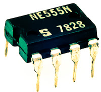
IC 555 timer tester is a simple circuit that serves to test the condition of IC 555. 555 timer circuit tester, in principle, start the timer 555 in astable multivibrator mode. As an indicator of the status of the timer 555 good condition or damaged to use 2 pieces LED which will light up in a blink alternately when the timer 555 in good condition.
And only one will turn on or off all the timer 555 when the condition is broken. 555 timer circuit tester is powered using 9 Volt DC voltage source. Complete circuit tester 555 as follows.
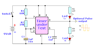 |
| Tester schematic |
How to use 555 timer tester is in conjuction with IC 555 to test the existing IC socket according to the orderbutton. Then activate the power switch to begin testing the 555 timer ic. Then live we observe the LED indicators 2buah before, whether flashing alternately (good) or not blink or even die all (timer 555 damaged).
Subscribe to:
Posts (Atom)