Showing posts with label voltage. Show all posts

Friday, January 10, 2014

The High Voltage Geiger Counter Supply Circuit Diagram

This High Voltage Geiger Counter Supply Circuit Diagram will generate about 300 volts dc —at a very low current, but enough for a GM tube. be careful with the output.


High Voltage Geiger Counter Supply Circuit Diagram

High Voltage Geiger Counter Supply Circuit Diagram

Continue reading...

Saturday, December 21, 2013

Precision Voltage Inverter Circuit Diagram

This Precision Voltage Inverter Circuit Diagram allows a reference to be inverted with 1 ppm accuracy, features high input impedance, and requires no trimming.

Precision Voltage Inverter Circuit Diagram 

Precision Voltage Inverter Circuit Diagram

Continue reading...

Friday, May 17, 2013

High Current 7812 Voltage Regulator

High current 7812 voltage regulator can be constructed by adding a transistor to increase load current capability. As contained in the manual 78/79xx three terminal voltage regulators, positive type of regulator used to use NPN transistors, and otherwise negative type use PNP transistors.

Here is an example of 12V DC voltage regulator circuit using IC 7812 which aims to improve the load current of 1A IC 7812 higher (15A). The more external transistor used the higher load currents

7812 Voltage Regulator Circuit


The voltage regulator circuit below has a current capability up to 15A load by adding three complementary transistors MJ2955. The load current capability can be changed by adding or reducing the number of MJ2955. Resistor 100R or lower can serve to prevent current swamping so as to stabilize the incoming voltage to the IC 7812.
High Current 7812 Voltage Regulator

Since 7812 no load current capability greater than 1A needs to be given as a safety fuse 1A output current over the IC, and protect it from high current transients. In IC 7812 and MJ2955 transistor heatsink should be installed so that there is enough heat reduction of the load current is used.

As the above circuit design can be applied to the negative regulator 7912. You need to replace the transistor MJ2955 with other types such as MJ3055, 2N3055 or TIP3055. Hopefully this brief overview is useful in increasing the load current of the 7812 voltage regulator.
Continue reading...

Friday, April 12, 2013

Simple Car Battery Voltage Monitor Circuit

This circuit is used to monitor the battery voltage to show a twin-colored LED standing of the battery to. If the LED “green”battery voltage exceeds eleven.9 volts. If the yellow LED, battery voltage 11.9 to 11.5 volts. If the LED is “red” If the battery voltage beneath 11.5 volts. You can after all trade the set off factors with the support of the trimmer resistors and / or altering the value of the resistors in the divider.


A dual op amp is used as a comparator. The inexperienced LED on the board, except the voltage exceeds 11.5 volts. The crimson LED illuminates when the voltage falls below eleven.9 volts to the circuit. Therefore, in the 11.9 to 11.5 volts, both LEDs are on, producing a relatively yellow colour. When the voltage falls below 11.5 V, the inexperienced LED, and now only the purple LED flashes to point low voltage.

Electronic Parts List
R1=1K2
R2-3-4=680R
R5=15K
R6=10K
R7-8-9-10=1K
IC1=LM324
D1=5V6 /0.5W Zener
D2-3-4-5=LED
RV1=10K trimmer

Is really helpful that multi-shaper for V1 and V2. Muti-trimmer makes it a lot more straightforward to trigger points to make as a inexpensive single-turn trimmer. The trimmer can be totally eradicated when you have get right of entry to to a range of 1% resistors and has had calculated carefully. You would additionally need to present more correct reference voltage as the widespread 78L05 regulator.

Continue reading...

Wednesday, April 10, 2013

Simple 7805 Voltage Regulator Circuit

A voltage regulator is used to produce a constant linear output voltage. It’s generally used with AC to DC power supply. And also it can be used as well as a DC to DC voltage converter . To regulating low voltage, most used device is one single IC. 7805, 7812, 7905 etc. 78xx series are design for positive and 79xx series are for Negative voltage regulator.

7805 is a three terminal +5v voltage regulator IC from 78XX chips family. See 7805 pinout below. LM78XX series are from National Semiconductor. They are linear positive voltage regulator IC; used to produce a fixed linear stable output voltage.  National Semiconductor has also negative voltage regulator chips family, they indicate with LM 79XX. 78xx is used more than 79xx because negative voltage has a few usability purposes as we see.
I was previously posted a 5v regulated power supply circuit using 7805 IC, that circuit and this 7805 voltage regulator circuit is almost the same.
 
 
Its output voltage is +5V DC that we need. You can supply any voltage in input; the output voltage will be always regulated +5V. But my recommendation is, don’t supply more than 18V or less than 8V in input. There used two capacitors in this voltage regulator circuit, they aren’t mandatory to use. But it will be best if you use them. They helped to produce a smooth regulated voltage at output. Use electrolyte capacitor instead of ceramic capacitor.

One limitation of 7805 I have found that is its output current 1A maximum. Otherwise it is a good voltage regulator if you are happy with 1A. But if   you need over 400mA current in output then you should use a Heat Sink with IC LM7805. Otherwise it may fall damage for overheating.Link
 
Continue reading...

Tuesday, April 9, 2013

Voltage Tester for Model Batteries

With a suitable load, the terminal voltage of a NiCd or lithium-ion battery is proportional to the amount of stored energy. This relationship, which is linear over a wide range, can be used to build a simple battery capacity meter.
Circuit Image :
 Voltage Tester for Model Batteries Image
Voltage Tester for Model Batteries Circuit Image 
This model battery tester has two functions: it provides a load for the battery, and at the same time it measures the terminal voltage. In addition, both functions can be switched on or off via a model remote-control receiver, to avoid draining the battery when it is not necessary to make a measurement. The load network, which consists of a BC517 Darlington transistor (T2) and load resistor R11 (15 Ω /5 W), is readily evident. When the load is active, the base of T1 lies practically at ground level. Consequently, T1 conducts and allows one of the LEDs to be illuminated.
Circuit Diagram :
Voltage Tester for Model Batteries-Circuit Diagram
Voltage Tester for Model Batteries Circuit Diagram
The thoroughly familiar voltmeter circuit, which is based on the LM3914 LED driver, determines which LED is lit. The values of R6 and R7 depend on the type and number of cells in the battery. The objective here is not to measure the entire voltage range from 0 V, but rather to display the portion of the range between the fully charged voltage and the fully discharged voltage. Since a total of ten LEDs are used, the display is very precise. For a NiCd battery with four cells, the scale runs from 4.8 V to 5.5 V when R6 = R7 = 2 kΩ. The measurement scale for a lithium-ion battery with two cells ranges from 7.2 V to 8.0 V if R6 = 2 kΩ and R7 = 1 kΩ.
For remote-control operation, both jumpers should be placed in the upper position (between pin 1 and the middle pin). In this configuration, either a positive or negative signal edge will start the measurement process. A positive edge triggers IC1a, whose output goes High and triggers IC1b. A negative edge has no effect on IC1a, but it triggers IC1b directly. In any case, the load will be activated for the duration of the pulse from monostable IC1b. Use P12 to set the pulse width of IC1a to an adequate value, taking care that it is shorter than the pulse width of IC1b.
If the voltage tester is fitted into a remote-controlled model, you can replace the jumpers with simple wire bridges. However, if you want to use it for other purposes, such as measuring the amount of charge left in a video camera battery, it is recommended to connect double-throw push-button switches in place of JP1 and JP2. The normally closed contact corresponds to the upper jumper position,while the normally open contact corresponds to the lower position.
Parts :
Resistors:
R1,R2 = 47kΩ
R3 = 100kΩ
R4 = 500kΩ
R5 = 1kΩ
R6,R7 = see text (1% resistors!)
R8 = 1kΩ5
R9 = 1kΩ2
R10 = 330Ω
R11 = 15Ω 5W
R12 = 15kΩ
P1 = 100kΩ preset
Capacitors:
C1 = 10nF
C2 = 100nF
Semiconductors:
D1-D10 = LED, red, high effi-ciency
T1 = BC557
T2 = BC517
IC1 = 74HC123
IC2 = LM3914AN
Miscellaneous:
PC1,PC2,PC3 = solder pin
JP1,JP2 = jumper or pushbutton
PCB Layout :
B. PCB Laout
Voltage Tester for Model Batteries PCB Layout


Continue reading...

Friday, April 5, 2013

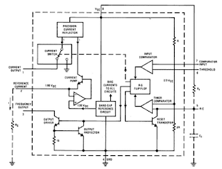
Voltage to frequency converters LM231 LM331

The LM231/LM331 family of voltage-to-frequency converters are ideally suited for use in simple low-cost circuits for analog-to-digital conversion, precision frequency-to-voltage conversion, long-term integration, linear frequency modulation or demodulation, and many other functions
Voltage-to-frequency converters LM231/LM331
Features Voltage-to-frequency converters LM231/LM331:
- Guaranteed linearity 0.01% max
- Improved performance in existing voltage-to-frequency
conversion applications
- Split or single supply operation
- Operates on single 5V supply
- Pulse output compatible with all logic forms
- Excellent temperature stability, ±50 ppm/°C max
- Low power dissipation, 15 mW typical at 5V
- Wide dynamic range, 100 dB min at 10 kHz full scale
- Wide range of full scale frequency, 1 Hz to 100 kHz
- Low cost
Continue reading...

Wednesday, April 3, 2013

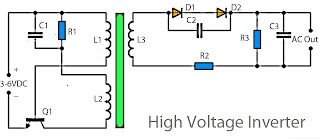
3V to High voltage inverter

Inverter circuit on basic of really taking a series of mosquito racket, a racket in which these mosquitoes require only a low voltage. With only 3 Volts course of this series has been able to work. Circuit is raising the voltage by a transformer that can be made yourself with the need of copper wire and ferrite rods.
high voltage inverter
How to making a transformer like that here, but this circuit requires a step-up transformer that are larger and require a lot of coils. This transformer is controlled by a transistor semiconductor 24D506 in this series. To output issued until 1KV or more but issued is very low amperage. This circuit can also be used in fluorescent lamps 10W maximum. When used in fluorescent lamps add another capacitor to the voltage for provoke can turn on the lights.
Part List :

Resistor
R1____1K5 Ω
R2____4K3 Ω
R3____22M Ω

Capacitor
C1____100n
C2____100n  400V
C3____0.2uF 400V


Diode
D1___1N4007
D2___1N4007

Transistor
Q1___ 24D506

Transformer
L1___#100 turns
L2___#100 turns
L3___#1000 turns
Making transformer like here.

high voltage inverter circuit
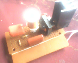
Project like this
Continue reading...

Saturday, March 30, 2013

Mini High Voltage Generator

Here’s a project that could be useful this summer on the beach, to stop anyone touching your things left on your beach towel while you’ve gone swimming; you might equally well use it at the office or workshop when you go back to work. In a very small space, and powered by simple primary cells or rechargeable batteries, the proposed circuit generates a low-energy, high voltage of the order of around 200 to 400 V, harmless to humans, of course, but still able to give a quite nasty ‘poke’ to anyone who touches it.  Quite apart from this practical aspect, this project will also prove instructional for younger hobbyists, enabling them to discover a circuit that all the ‘oldies’ who’ve worked in radio, and having enjoyed valve technology in particular, are bound to be familiar with. As the circuit diagram shows, the project is extremely simple, as it contains only a single active element, and then it’s only a fairly ordinary transistor. As shown here, it operates as a low-frequency oscillator, making it possible to convert the battery’s DC voltage into an AC voltage that can be stepped up via the transformer.  

Using a centre-tapped transformer as here makes it possible to build a ‘Hartley’ oscillator around transistor T1, which as we have indicated above was used a great deal in radio in that distant era when valves reigned supreme and these was no sign of silicon taking over and turning most electronics into ‘solid state’. The ‘Hartley’ is one of a number of L-C oscillator designs that made it to eternal fame and was named after its invertor, Ralph V.L Hartley (1888-1970). For such an oscillator to work and produce a proper sinewave output, the position of the intermediate tap on the winding used had to be carefully chosen to ensure the proper step-down (voltage reduction) ratio.  Here the step-down is obtained inductively. Here, optimum inductive tapping is not possible since we are using a standard, off-the-shelf transformer. However we’re in luck — as its position in the centre of the winding creates too much feedback, it ensures that the oscillator will always start reliably. 

However, the excess feedback means that it doesn’t generate sinewaves; indeed, far from it. But that’s not important for this sort of application, and the transformer copes very well with it.  The output voltage may be used directly, via the two current-limiting resistors R2 an R3, which must not under any circum-stances be omitted or modified, as they are what make the circuit safe. You will then get around 200 V peak-to-peak, which is already quite unpleasant to touch. But you can also use a voltage doubler, shown at the bottom right of the figure, which will then produce around 300 V, even more unpleasant to touch. Here too of course, the resistors, now know as R4 and R5, must always be present. The circuit only consumes around a few tens of mA, regardless of whether it is ‘warding off’ someone or not! If you have to use it for long periods, we would however recommend powering it from AAA size Ni-MH batteries in groups of ten in a suitable holder, in order not to ruin you buying dry batteries.

Circuit diagram:
mini-high-voltage-generator-circuit diagram
Mini High-Voltage Generator Circuit Diagram
Warning!
If you build the version without the voltage doubler and measure the output voltage with your multimeter, you’ll see a lower value than stated. This is due to the fact that the waveform is a long way from being a sinewave, and multimeters have trouble interpreting its RMS (root-mean-square) value. However, if you have access to an oscilloscope capable of handling a few hundred volts on its input, you’ll be able to see the true values as stated. If you’re still not convinced, all you need do is touch the output terminals... 

To use this project to protect the handle of your beach bag or your attachecase, for example, all you need do is fix to this two small metallic areas, quite close together, each connected to one output terminal of the circuit. Arrange them in such a way that unwanted hands are bound to touch both of them together; the result is guaranteed! Just take care to avoid getting caught in your own trap when you take your bag to turn the circuit off!
..::: Do not built this circuit if your not an EXPERT :::..

Streampowers
Continue reading...

Thursday, March 28, 2013

Simple 110 and 220V AC LED Voltage Indicator

This circuit, designed on request, has proven to be useful to indicate when the voltage in a power supply line is changing from 120V to 240Vac. It can be used in different circumstances and circuits, mainly when an increase in ac or dc supply voltage needs to be detected. D3 illuminates when the line voltage is approaching 120V and will remain in the on state also at 240V supply. On the other hand, D6 will illuminate only when the line voltage is about 240V and will stay on because the latching action of Q1, Q2 and related components. C1, D1 and D2 provide a low dc voltage in the 4.5V - 6V range in order to allow proper operation of latch circuit and LEDs.

Circuit diagram


Parts:

  • R1_____________470R 1/2W Resistor
  • R2_____________220K 1/4W Resistor
  • R3,R7__________470R 1/4W Resistors
  • R4_______________1K 1/4W Resistor
  • R5_______________2K2 1/4W Resistor
  • R6_____________330R 1/4W Resistor
  • C1_____________330nF 630V Polyester Capacitor
  • C2______________10µF 25V Electrolytic Capacitor
  • D1,D2________1N4007 1000V 1A Diode
  • D3,D6___________LEDs (Color and shape at will)
  • D4_________BZX79C10 10V 500mW Zener Diode (See Notes)
  • D5___________1N4148 75V 150mA Diode
  • Q1____________BC547 45V 100mA NPN Transistor
  • Q2____________BC557 45V 100mA PNP Transistor

Notes:

  • D4 value could require some adjustment in order to allow precise switching of the circuit at the chosen voltage. If the case, please try values in the 8.2V - 15V range.
  • Warning! The circuit is connected to 240Vac mains, then some parts in the circuit board are subjected to lethal potential! Avoid touching the circuit when plugged and enclose it in a plastic box.
Continue reading...

Wednesday, March 20, 2013

Voltage Inverter Using Switch Mode Regulator

This circuit uses a step-up switch-mode regulator, which is usually used to produce a positive supply, to generate a regulated negative output voltage. The device used here is the MIC4680 from Micrel (www.micrel.com), but the idea would of course work with similar regulators from other manufacturers. Because of coil L1, which performs the voltage conversion by the intermediate storage of energy in the form of a magnetic field, the output is effectively isolated from the input. We can therefore connect the right-hand side of L1 to ground rather than to the positive output without causing a large current to flow. Then we connect the ground pin of the regulator IC and all the components connected to it as the negative voltage output, isolated from ground.

Voltage Inverter Using Switch-Mode Regulator

The components on the output side of the regulator are connected as usual: flywheel diode D1, coil L1 and the voltage divider formed by R1 and R2. These last two components set the output voltage, according to a formula given in the data sheet. Example component values for the MIC4680 used here are given in the table. The input voltage should lie within the permitted range for the regulator used, and must in any case be at least as great in magnitude as the desired output voltage (here +5 V or +12 V), so that the step-down regulation technique can wor.

Voltage Inverter Using Switch-Mode Regulator Table
It is important to take care when building this circuit to mount the regulator using an insulator, since generally the GND pin of the device is connected to the heatsink tab. Also, the ON/OFF control input cannot be driven using a normal logic signal, since the regulator’s ground reference is the output voltage rather than ground itself. If the ON/OFF function is required, a level shifter or optocoupler must be used.

Source: http://www.ecircuitslab.com/2011/06/voltage-inverter-using-switch-mode.html 
Continue reading...