Showing posts with label audio. Show all posts
Showing posts with label audio. Show all posts
Tuesday, December 24, 2013
TV audio video transmitter Schematic Diagram
This is a simple TV audio video transmitter circuit can be constructed using this schematic diagram . This TV audio video transmitter circuit can be used to transmit video signals from VCR ( or some other device ) to a TV without using any cable .
Video signals input at jack J1 are first terminated by resistor R6 and coupled through capacitor C1 to clamping-diode D1. Potentiometer R3 is used to set the gain of the video signal; its effect is similar to that of the contrast control on a TV set.
TV audio video transmitter Schematic Diagram

Bias-control R7 can be used to adjust the black level of the picture so that some level of signal is transmitted, even for a totally dark picture.
RF-transformer T1 and its internal capacitor form the tank circuit of a Hartley oscillator thats tuned to 4.5 megahertz. Audio signals input at J2 are coupled to the base of Q3 via C2 and R4: the audio signal modulates the base signal of Q3 to form an audio subcarrier that‚s 4.5-megahertz higher than the video-carrier frequency.
The FM modulated subcarrier is applied to the modulator section through C5 and R9.
Resistor R9 adjusts the level of the subcarrier with respect to the video signal.
Resistor R9 adjusts the level of the subcarrier with respect to the video signal.
Transistors Q1 and Q2 amplitude modulate the video and audio signals onto an RF-carrier signal. The operating frequency is set by coil L4, which is 3.5 turns of 24- gauge enameled wire on a form containing a standard ferrite slug.
The RF output from the oscillator (L4, C7 and C9 ) section is amplified by Q5 and Q6, whose supply voltage comes from the modulator . Antenna matching and low-pass filtering is performed by C12, C13, and L1.
Resistor R12 is optional; it is added to help match the output signal to any kind of antenna.
To align this audio video transmitter you need to tune a TV receiver to an unused channel between 2 and 6. The TV must have an indoor antenna connected directly to it; an outdoor antenna or cable wont work. Make sure both potentiometers (R3, R7) are in middle position and apply power to the transmitter. Adjust L4 with a nonmetallic tool until the TV screen goes blank ,then fine-adjust L4 for the "most-blank" picture.
Connect the video and audio outputs from a VCR(AV source) to jacks J1 and J2 (respectively) of the transmitter .
After that you should see a picture on the TV screen: if you do, readjust L4 for the best picture; if you dont, check the board for any bad connections. Next, adjust R3 for the best picture brightness and R7 for the best overall picture.
Finally, adjust T1 with a nonmetallic tool for the best sound .
The TV transmitter combines line level audio and video signals, and transmits the resulting signal up to 300 feet. The circuit can be powered from a 9-12V power supply circuit .

Monday, September 2, 2013
1W Audio Amplifier Using NCP2830
This 1w audio amplifier circuit is designed using NCP2830 audio IC manufactured by ON Semiconductor.This audio power amplifier ic designed for portable communication device applications and require few external electronic components.
1W Audio Amplifier Circuit using NCP2830

NCP2830 is capable to provide 1W continuous output power in 8 ohms load.NCP2830 audio power amplifier main features are : high quality audio (THD+N = 0.04%) , low noise: SNR up to 100 dB, overall system efficiency optimization: up to 89% , Superior PSRR (−88 dB): Direct Connection to Battery , Very Low Quiescent Current 7 mA , Optimized PWM Output Stage: Filterless Capability , Selectable gain of 2 V/V or 4 V/V .
1W Audio Amplifier Circuit using NCP2830

Thursday, April 11, 2013
5 8 Watt audio power amplifier

This amplifier circuit has a power output of a small or too low at 5.8 Watt, which uses IC KA2205. The required voltage for at least 6 volts to 18 volts DC maximum.
Schematics power audio amplifier with IC KA2205
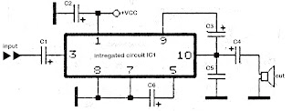
Component List
C1 = 1uF
C2 = 100uFC3 = 47uF
C4 = 1000uFC5 = 0.1uF
C6 = 220uF
IC1 = KA2205
Tuesday, April 9, 2013
TDA2822 made for 5 1 audio amplifier system
Skema Rangkaian Circuit combination of the 3 IC TDA2822 above can be used for 5.1 audio power amplifier system with low power output . The input signal used is analog signal not digital (SPDIF) , so it needed some input to the jack input. The speakers are suitable for use have impedance 8 Ohms , and with power 4 Watt, to Left , Right , Rear pair , center , and subwoofer speakers. To run this circuit , is also required circuit for volume control as tone control.

Component and technical Information :
C1-C6 : 220uF/25V
C7-C9 : 47uF/16 V
IC : TDA2822 x3
CON-1: VCC +12volts DC
CON-2: Ground
CON-3: Left Speaker
CON-4: Right Speaker
CON-5: Rear Speaker
CON-6: Rear Speaker
CON-7: Center Speaker
CON-8: Subwoofer Speaker
X1-1:Ground
X1-2:Subwoofer Input
X1-3:Center Input
X1-4:Rear Input
X1-5:Rear Input
X1-6:Right Input
X1-7:Left Input
See this Printed circuit board below:

circuit and PCB Design use Cadsoft Eagle Software
Sunday, March 31, 2013
Three Channel Audio Splitter
Simple circuitry, Passive high-quality amplification and distribution
This circuit is suitable to amplify and distribute the audio signals. The input audio signal is applied to the J1 and after passing through the P1, It is buffered and amplified by the IC1 prepared to redistribute. It has 3 outputs to drive 3 audio lines with 300 ohms impedance.
Circuit Diagram:

Three Channel Audio Splitter Circuit Diagram
Parts:
J1 = RCA Socket (See Notes)
P1 = 100K-Potentiometre
R* = 10K-100K
R1 = 560K
R2 = 1K
R3 = 2.2K
R4 = 2.7K
R5 = 2.7K
R6 = 330R
R7 = 330R
R8 = 330R
C1 = 100uF-25V
C2 = 100uF-25V
C3 = 100uF-25V
D1 = BZX79C18
D2 = BZX79C18
Q1 = BC337
Q2 = BC327
IC1 = NE5532-34
Notes:
- J1 will be RCA Audio input female socket.
- R* is on your choice it can be choose between 10K to 100K resistor.
- Output capacitor’s value is between 100uf to 470uf and power handling is 25V to 50V.
- You can power up this circuit via +12V/-12V regulated supply but you have to remove following parts Q1-Q2-C2-C3-D1-D2.
- Maximum power ratings +35V/-35V
Source : www.extremecircuits.net
Wednesday, March 27, 2013
Apprentice Added Audio Capacitors Assignment Bang

New System Help Me Honda Prelude Forum.

Dianz Capacitors Diagram Of Ceramic Capacitors.

Car Audio Systems Explained.

Pioneer Deh P6400 Wiring Diagram Group Picture Image By Tag.

Kenwood Radio Wiring Diagram Ajilbab Com Portal.

Audio Wiring Diagram 1989 Gt Mustang Ford Mustang Forums.

Apprentice Added About How Car Audio Capacitors Assignment Bang Here.

Or Perhaps A Car Stereo Wiring Diagram Installing Electronics Can Be.

2005 Silverado Radio Wiring Car Diagrams 2005 Silverado Radio Wiring.

My Car Audio System.
Subscribe to:
Posts (Atom)