Showing posts with label watt. Show all posts
Showing posts with label watt. Show all posts
Thursday, April 11, 2013
5 8 Watt audio power amplifier

This amplifier circuit has a power output of a small or too low at 5.8 Watt, which uses IC KA2205. The required voltage for at least 6 volts to 18 volts DC maximum.
Schematics power audio amplifier with IC KA2205
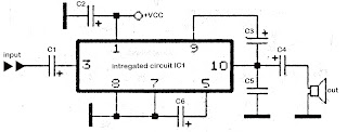
Component List
C1 = 1uF
C2 = 100uFC3 = 47uF
C4 = 1000uFC5 = 0.1uF
C6 = 220uF
IC1 = KA2205

Thursday, March 28, 2013
Buck Converter 1 Watt White LED Driver

This is an example of efficiently driving a 1 watt white LED from a 12 volt
 battery using a buck converter. The LED could simply be connected with a
 series resistor to get the desired current, but the efficiency would be
 only 25% since the resistor would drop 9 volts while the LED only requires
 3. The buck converter provides about 90% efficiency.

 The idea is to establish a circulating current through the inductor, diode
 and load, while the switch replenishes the lost load energy on each cycle.
 The duty cycle of the switch will be the output voltage divided by the input
 voltage, or about 3/12  (25%) in this case. Its actually a little greater
 since there is a small (2.2 ohm) resistor in series with the LED that drops
 about 0.5 volt, so the total load is about 3.7 volts and the duty cycle is
 around 31%. The circuit could also be used to charge AA batteries from a
 12 volt source with adjustment to the duty cycle.

 The driver section uses a CMOS hex inverter (CD4069) where two of the
 inverters form an oscillator with 31% duty cycle at about 11.5 Khz,
 or 66us off time, and 21uS on time for the MOSFET switch. The remaining 4
 inverters are used in parallel to provide additional drive current to
 the gate of the MOSFET. The duty cycle can be adjusted with either the
 15K or 20K resistors.

 The minimum inductor value was worked out from E = L * di/dt and a LED
 current of 250mA. The minimum value is where the current falls to 0 during
 the switch off time, or 66uS. The peak inductor current would then be twice
 the average or 500mA and the inductor will charge from 0 to 500mA in 21uS.
 So, di/dt is 0.5 /.000021 = 23810 amps per second. The inductor voltage
 (E) will be 12 minus the load voltage 3.7 or 8.3 volts and the minimum
 inductor value L will be 8.3 / 23810 = 0.35 mH. The actual value used should
 be somewhat higher to avoid the current falling to zero and to avoid large
 peak currents and possible saturation. The example here uses a approximate
 2 mH inductor so the change in current is about 100mA and the peak current
 is lower at about 300mA. The current waveform is shown in the LTspice
 picture below. Notice the current ramps from about 50mA below the average
 current to about 50mA above the average or about 100mA total change. The
 15 ohm resistor in the LTspice picture represents the LED plus a 2.2 ohm
 resistor. The MOSFET is represented by the SW (switch) component, and the
 drive circuit by the V3 symbol.

The inductor (pictured below) should be rated for saturation current of more than the peak current, or maybe 300mA in this case. The toroid inductor used is fairly large for the task measuring about 1.5 inches diameter with 20 turns of #18 wire. The core is conductive so it probably should be taped in case the wire insulation fails. The picture shows the naked core for illustration. A smaller core with an air gap could be used to avoid saturation, but would require more wire which would add to the losses due to the wire resistance. Another approach is to use a higher frequency so smaller inductors can be used. But this will add to losses since there would be more switching transitions per unit of time, which adds to the loss. The diode is a VSK330 schottky 3 amp variety for low loss, but most any 1 amp rectifier could be used with somewhat less efficiency. The IRFZ44 MOSFET is also an overkill rated at 50 amps max but very low on-resistance of only 28 milliohms. A much smaller device could be used, but I dont have the numbers. Note the circuit has no regulation, so the 12 volt input should be stable. If the battery voltage varies, the duty cycle and LED current should be set using the highest expected supply voltage.

link
Friday, March 22, 2013
Making a 40 Watt LED Emergency Tubelight Circuit Using 1 Watt 350 mA LEDs
The article explains a simple yet effective 40 watt LED emergency tube light circuit which can be installed at home for acquiring uninterruptible illumination at the same time saving a lot of electricity and money.
You might have reads one of my earlier articles which explained a 40 watt LED street light system. The power saving concept is pretty much the same, through a PWM circuit, however the alignment of the LEDs has been laid in a completely different manner here.
As the name suggest the present idea is of an LED tube light and therefore the LEds have been configured in a straight horizontal pattern for better and efficient light distribution.
The circuit also features an optional emergency battery back up system which may be employed for getting an uninterruptible illumination from the LEDs even during the absence of normal mains AC. Due to the PWM circuit the acquired backup can extend up to more than 25 hours on every single recharge of the battery (rated at 12V/25AH).
The PCB would be strictly needed for assembling the LEDs. The PCB must be an aluminum-back type. The track layout is shown in the below given picture. As can be seen the LEDs are spaced at a distance of about 2.5 cm or 25mm from each other for enhancing maximum and optimal distribution of light.
Either the LEDs may be laid over a single row or over a couple of rows.
A single row pattern is shown in the below given layout, due to lack of space only two series/parallel connection has been accommodated, the pattern is continued further on the right side of the PCB so that all the 40 LEDs become included.

Normally the proposed 40 watt LED tube light circuit, or in other words the PWM circuit may be powered through any standard 12V/3amp SMPS unit for the sake of compactness and decent looks.
After assembling the above board, the output wires should be connected to the below shown PWM circuit, across the transistor collector and positive. The supply voltage should be provided from any standard SMPS adapter as mentioned in the above section of the article. The LED trip will instantly light up illuminating the premise with flood light brightness. The illumination may be assumed to be equivalent to a 40 watt FTL with power consumption of less than 12 watts, thats a lot of power saved.
Emergency Battery Operation
If an emergency backup is preferred for the above circuit, it may be simply done by adding the following circuit.
Lets try to understand the design in more details:

The circuit shown above is the PWM controlled 40 watt LED lamp circuit, the circuit has been elaborately explained in this article. You can refer it for knowing more about its circuit functioning.
The next figure shown below is an automatic under voltage and over voltage battery charger circuit with automatic relay changeovers. The whole functioning may be understood with the following points:
 The IC 741 has been configured as a low/high battery voltage sensor and it activates the adjoining relay connected to the transistor BC547 appropriately.
Assume the mains to be present and the battery to be partially discharged. The voltage from the AC/DC SMPS reaches the battery through the N/C contacts of the upper relay which remains in an deactivated position because of the battery voltage which may be below the full charge threshold level, lets assume the full charge level to be 14.3V (set by the 10K preset).
Since the lower relay coil is connected to the SMPS voltage, stays activated such that the SMPS supply reaches the PWM 40 watt LED driver via the N/O contacts of the lower relay.
Thus the LEDs remains switched ON by using the DC from the mains operated SMPS adapter, also the battery continues to get charged as explained above.
Once the battery gets fully charged, the output of the IC741 goes high, activating the relay driver stage, the upper relay switches and instantly connects the battery with the N/C of the lower relay, positioning the battery in the standby condition.
However until AC mains is present, the lower relay is unable to deactivate and therefore the above voltage from the charged battery is not able to reach the LED board.
Now if suppose AC mains fails, the lower relay contact shifts to the N/C point, instantly connects the supply from the battery to the PWM LED circuit, illuminating the 40 watt LEDs brightly.
The LEDs consume battery power until either the battery falls below the low voltage threshold or mains power is restored.
The low battery threshold setting is done by adjusting the feedback preset 100K across the pin3 and pin6 of the IC741.
You might have reads one of my earlier articles which explained a 40 watt LED street light system. The power saving concept is pretty much the same, through a PWM circuit, however the alignment of the LEDs has been laid in a completely different manner here.
As the name suggest the present idea is of an LED tube light and therefore the LEds have been configured in a straight horizontal pattern for better and efficient light distribution.
The circuit also features an optional emergency battery back up system which may be employed for getting an uninterruptible illumination from the LEDs even during the absence of normal mains AC. Due to the PWM circuit the acquired backup can extend up to more than 25 hours on every single recharge of the battery (rated at 12V/25AH).
The PCB would be strictly needed for assembling the LEDs. The PCB must be an aluminum-back type. The track layout is shown in the below given picture. As can be seen the LEDs are spaced at a distance of about 2.5 cm or 25mm from each other for enhancing maximum and optimal distribution of light.
Either the LEDs may be laid over a single row or over a couple of rows.
A single row pattern is shown in the below given layout, due to lack of space only two series/parallel connection has been accommodated, the pattern is continued further on the right side of the PCB so that all the 40 LEDs become included.
Normally the proposed 40 watt LED tube light circuit, or in other words the PWM circuit may be powered through any standard 12V/3amp SMPS unit for the sake of compactness and decent looks.
After assembling the above board, the output wires should be connected to the below shown PWM circuit, across the transistor collector and positive. The supply voltage should be provided from any standard SMPS adapter as mentioned in the above section of the article. The LED trip will instantly light up illuminating the premise with flood light brightness. The illumination may be assumed to be equivalent to a 40 watt FTL with power consumption of less than 12 watts, thats a lot of power saved.
Emergency Battery Operation
If an emergency backup is preferred for the above circuit, it may be simply done by adding the following circuit.
Lets try to understand the design in more details:
The circuit shown above is the PWM controlled 40 watt LED lamp circuit, the circuit has been elaborately explained in this article. You can refer it for knowing more about its circuit functioning.
The next figure shown below is an automatic under voltage and over voltage battery charger circuit with automatic relay changeovers. The whole functioning may be understood with the following points:
Assume the mains to be present and the battery to be partially discharged. The voltage from the AC/DC SMPS reaches the battery through the N/C contacts of the upper relay which remains in an deactivated position because of the battery voltage which may be below the full charge threshold level, lets assume the full charge level to be 14.3V (set by the 10K preset).
Since the lower relay coil is connected to the SMPS voltage, stays activated such that the SMPS supply reaches the PWM 40 watt LED driver via the N/O contacts of the lower relay.
Thus the LEDs remains switched ON by using the DC from the mains operated SMPS adapter, also the battery continues to get charged as explained above.
Once the battery gets fully charged, the output of the IC741 goes high, activating the relay driver stage, the upper relay switches and instantly connects the battery with the N/C of the lower relay, positioning the battery in the standby condition.
However until AC mains is present, the lower relay is unable to deactivate and therefore the above voltage from the charged battery is not able to reach the LED board.
Now if suppose AC mains fails, the lower relay contact shifts to the N/C point, instantly connects the supply from the battery to the PWM LED circuit, illuminating the 40 watt LEDs brightly.
The LEDs consume battery power until either the battery falls below the low voltage threshold or mains power is restored.
The low battery threshold setting is done by adjusting the feedback preset 100K across the pin3 and pin6 of the IC741.
Subscribe to:
Posts (Atom)